Showing posts with label Automobiles. Show all posts

Emission Control Systems

Respons: 4 comments
If not controlled, the automobile can give off pollutants from four places. Pollutants can come from the fuel tank, the carburetor, the crankcase, and the tail pipe. Pollutants from the fuel tank and carburetor consist of gasoline vapors. Pollutants from the crankcase consist of partly burned air-fuel mixture that has blown by the piston rings. Pollutants from the tail pipe consist of partly burned gasoline (HC), carbon monoxide (CO), nitrogen oxides (NOx), and if there is sulfur in the gasoline, sulfur oxides (SOx).
Emission Control Systems
A portion ò the air-fuel mixture remains incompletely burned during the combustion process. This incomplete combustion results in the formation of hydrocarbons (HC), and oxides of nitrogen (NOx). Excessive amounts of these emissions form a major contribution to atmospheric pollution and can constitute a serious health hazard.

Almost two-thirds of the emissions produced in the combustion process are carried away from the engine and expelled into the atmosphere through the automobile exhaust system. It is impossible to seal off the exhaust system because any attempt to stop the flow of exhaust gases would produce a backpressure that would stop the combustion process. Consequently, research has been directed toward reducing the harmful emission contained in the exhaust as to as low a level as possible.

Many common causes of excessive emissions can be attributed to a malfunctioning engine or engine auxiliary system. Some authorities estimate that it is possible to cut emissions by as much as 50 to 60 percent if the vehicle is properly tuned. A further reduction of emissions depends on the use of specially designed emission control systems.

Approximately 15 percent of the vehicle emissions that contribute to atmospheric pollution are in the form of vapors tat escape from the fuel tank and carburetor float bowl. Most evaporative fuel losses occur at the fuel tank and result from the expansion and contraction of air in the tank as the tank heats up or cools. The expanding air escapes through the tank vent tube or vented cap, carrying fuel vapors with it.

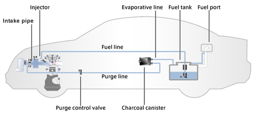
Several different evaporative emission control systems have been developed to prevent the loss of fuel vapors to the atmosphere. In general, these are closed systems which provide for the return of fuel vapors from the fuel tank and carburetor to the engine where they are burned. As such, these systems are sometimes called fuel-vapor recovery systems or canister storage systems. Depending on the type of system, the fuel vapors are first collected and stored either in a charcoal canister or in the engine crankcase.

Some evaporative emission –control systems use a charcoal canister as the storage receptacle for the fuel vapors. The General Motors fuel-vapor recovery system is an example of this type. This system consists of a special fuel tank, vacuum/pressure filler cap, vapor/liquid separator standpipe assembly, carbon canister, canister purge hoses, and a modified carburetor. Fuel vapors that would ordinarily escape to the atmosphere are directed into the canister by venting the fuel tank (or, in some applications, by venting the carburetor float bowl as well) where they are absorbed by the charcoal and stored until use. The fuel vapor is removed from the canister by manifold vacuum and burned in the engine.

A carbon (vapor) canister is an integral part of a gasoline engine fuel vapor recovery system. These canisters may be classified as open-bottom or closed-bottom.

A three-tube canister provides for venting both the fuel tank and the carburetor float bowl. Fuel vapors in the float bowl flow through a hose to a third tube and are absorbed by the carbon. The purging method is identical to the one for a two-tube canister

The three-tube canister has been improved to prevent venting of the carburetor float bowl during engine operation. A spring-biased diaphragm valve, which is normally open, controls the flow of fuel vapors from the carburetor to the canister. When the engine is not running, spring tension holds the valve open, allowing normal venting. When the engine is started, manifold vacuum pulls the diaphragm up to close the valve.

In the road-cirafuventilation system, openings at both the front and back of tube crankcase are used to provide a through-pas-sage for ventilation. The front opening con-nects to the oil filter cap and the opening at the back of the crankcase connects to a road-draft tube. Forward movement of the vehicle creates slight vacuum at the road-draft tube opening and a slight pressure of air around the oil filler pipe located under the hood. These pressure differences draw in fresh air to ventilate the crankcase and suck the fule and exhaust fumes into the air cleaner or intake manifold.

Unlike the road-draft system, the positive-crankcase-venti-lation system (PCV) does not rely on vehicle movement for its operation, but instead uses manifold vacuum to maintain a positive movement of air through the crankcase at all engine speeds this greatly reduces the accumulation of harmful deposits when driving in heavy, stop-and –go traffic. The PCV system also results in increased gas mileage because the fuel vapors from the crankcase are drawn into the engine and burned instead of being lost to the atmosphere.

Fresh air enters the system from the clean-air side of the air cleaner or through a separate breather filter. Because intake-manifold vacuum is used to operate the PCV system, the PCV flow into the intake manifold must be regulated so that it varies in proportion to the regular air-ruel ratio being drawn into the intake manifold through the car-buretor. A PCV valve is used to regulate the airflow through the system and into the intake manifold. It is designed to vary the amount of airflow according to the various modes of engine operation

A plunger-type PCV valve consists of a coil spring, plunger, and a valve body. The amount of PCV valve opening or restriction is governed by the amount of vacuum present in the intake manifold. High vacuum overcomes the force of the valve spring and causes the plunger to bottom in the manifold end of the valve housing, thereby restricting the airflow to the intake manifold. At low vacuum, the spring force is stronger than the vttcuum pull, and the valve plunger is forced toward the crankcase end of the valve housing, allowing greater airflow to the intake manifold.

Fuel System Troubles

Respons: 1 comments
Fuel System Troubles
Experience gained in operating automotive engines has shown that most engine troubles rest with the fuel system. The more common fuel system troubles are fuel leaks through badly sealed fuel line connections, air leaks past air cleaners and filters, and clogged fuel lines and filters. Besides, carburetor engines may suffer from carburetor troubles resulting in inadequate air-fuel mixture composition (too lean or too rich); diesel engines may develop troubles due to air finding its way into the fuel lines, poor atomization of fuel by the fuel injector, or wrong injection timing.

Such trouble may cause hard starting, lack of power, misfiring, smoky exhaust, or sudden stalling.

Fuel leaks can be detected by visual injection. The leaks, if revealed, are eliminated by tightening up the leaky connections or by replacing defective gaskets.

If the engine does not start, the first thing to do is to make sure that there is fuel in the tank and that the fuel shut-off cock is open. Then check the operation of the fuel (transfer) pump and make sure that the fuel lines and filters are not clogged. Use a tire pump to clear clogged fuel lines, if any. Next check the carburetor (if your engine uses one) for clogged jets. Use a tire pump to clear clogged carburetor jets, if found. Never use wire to do the job. For this may damage jet orifices.

A diesel engine will not start if air gets into the fuel system, for in this case, the fuel-injection pump will compress air bubbles in its barrels instead of delivering fuel into the engine cylinders. Should this prove to be the case, bleed the fuel system, using the hand primer pump. Expel air first from the primary fuel filter, then from the secondary fuel filter, and finally from the fuel-injection pump head.

Wrong injection timing may also be the cause of hard starting. Therefore, check for this condition as well and make corrections, if necessary.

Should all the above corrective measures prove to be no help, check the fuel injector for spray pattern and injection pressure, and replace any one found to be defective. Still better, replace the injectors outright, if spares are available.

If a diesel engine lacks power and, in addition, misses or has a smoky exhaust, one should first of all locate the cylinder that is most responsible for these troubles. To do this, disconnect each fuel injector in turn from the fuel-injection pump. This can be done by backing off 1. 5 to 2 turns the injection-line union nuts on the pumping elements. The disconnection of any injector, except for the one in the misfiring cylinder, will affect the operation of the engine.

Loss of power that is not coincidental with an increased exhaust density is most probably caused by clogged fuel filter or worn pump plunger-and-barrel or injector nozzle-and-needle-valve assemblies. Therefore, the first thing to do in this case is to check the primary and secondary fuel filters and wash their filter elements, if necessary.

A reduction in engine power not attended by a smoky exhaust may be caused by a faulty fuel injector, clogged air cleaner, or incorrect injection timing. So, check the air cleaner and, if necessary, wash the oil path and screen filters with diesel fuel. Fill the bath with fresh oil. Check and adjust (if necessary) the injection timing.

Never disassemble the fuel injectors or fuel-injection pump under field conditions. Any operations involving the disassembly of these units can only be done by skilled mechanicians at specialized shops.

In carburetor engines, loss of power, resulting from defects in the fuel system, is due to an air-fuel mixture that is either too lean or too rich.

A lean mixture condition may result from either too little fuel or too much air in the combustible charge. The amount of fuel in the charge may be reduced because of clogged fuel tank air vent, clogged fuel lines, filters or carburetor fuel jets, defective fuel pump or too low fuel level in the carburetor float chamber. An increased amount of air in the charge may be due to carburetor body and intake manifold air leaks.

The clogged fuel tank air vent should be cleared from dirt or ice (in winter time). Clogged fuel filters should be disassembled, cleaned and washed in clean gasoline. Damaged fuel pump diaphragms should be replaced. Poorly fitting fuel pump valves should be cleaned and, if necessary, replaced. Air leaks should be eliminated by tightening the carburetor body and intake manifold fasteners or by replacing damaged sealing gaskets.

A rich mixture will also cause a loss of power. Excessive quantities of fuel will not vaporize and burn completely. Liquid fuel washes the lubricant from the cylinder walls, allowing the piston rings to make metal-to-metal contact. Scuffed rings and excessive oil and fuel consumption will result.

An excessively rich mixture may result from defects in the carburetor and also from too high a fuel pressure which forces the carburetor needle valve off its seat, causing flooding.

An engine may show a loss in power when unfiltered-air enters the cylinders, causing increased wear in the piston rings and cylinder liners. Pistonring wear results in poor compression, hard starting and increased exhaust smoke density. Therefore, the engine should be systematically checked for air-intake leaks.

A diesel engine will race (i. e., develop excessively high speed) if there is too much oil in the governor housing or in the oil bath of the air cleaner, or else if the fuel control rack or some governor components are frozen. In this case, the engine must be stopped and the condition causing the trouble must be remedied.

Engine Speed Governing

Respons: 0 comments
During operation, the load on the engine of an automobile frequently varies, depending on the ambient conditions (lay of the ground, soil condition, etc.). These load variations cause the engine speed to change accordingly, provided the position of the throttle valve or fuel control rack remains unchanged.

When the load on the engine is decreased, the engine speed may rise beyond safe limits, causing accelerated wear of the engine working parts and increased fuel consumption. A device for automatically controlling the speed of an engine by regulating the intake or injection of fuel, so that the engine speed is maintained at the desired level under all conditions of loading, is termed the governor.

Governor control may be effected by centrifugal (mechanical), hydraulic, pneumatic or combined (pneumatic-centrifugal) means. Speed governors may be classed as speed-limiting, constant-speed or all-speed. Speed-limiting and constant-speed governors are used on automobile engines and on auxiliary engines employed for starting tractor diesel engines. An automobile governor is in essence a maximum-speed governor.

The automobile maximum-speed governor is of pneumatic-centrifugal type. It comprises two mechanisms: centrifugal governor sender and diaphragm-operated governor actuator. The centrifugal governor sender includes a rotor whose shaft receives the rotation from the engine camshaft. The sender unit is mounted on the timing gear cover. The rotor houses the valve which is pulled away from its seat by a spring.

The governor actuator includes a diaphragm which is connected by a rod to one end of the bell-crank. The other end of the bell-crank is connected with the governor spring. The bell-crank is fixed to the throttle spindle. The throttle control mechanism incorporates a special claw coupling which enables the governor actuator to close and open the throttle valve irrespective of the position of the accelerator pedal. The spaces above and below the diaphragm are interconnected through the governor sender by pipes. On the other hand, the space above the diaphragm communicates with the carburetor chamber below the throttle valve and that below the diaphragm, with the space below the choke valve, via passages.

So long as the engine speed remains below the preset maximum (3200 rpm), the centrifugal force of the valve is insufficient to overcome the tension of the spring, and so the valve stays open. As a result, the space above and below the diaphragm communicate with each other through the governor sender. When the maximum speed is attained, the centrifugal force of the valve overcomes the resistance offered by the spring, and the valve closes ott to its seat, thus breaking communication between the spaces above and below the actuator diaphragm. This action causes the depression communicated from the carburetor chamber to the space above the diaphragm, via the lower passage, to grow higher. If the engine speed increases further, this depression becomes sufficiently high for the diaphragm to deflect upward against the governor spring force and close the throttle valve cy a certain amount, thus reducing the engine speed.

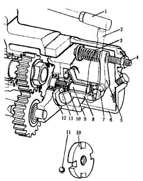
The main component parts of the governor are a housing, a shaft with a drive disk, a spring, and ball-shaped weights (balls) (Fig. 9)

The Governor housing is held to the engine crankcase through the medium of an adaptor plate. The governor shaft notates together with the drive disk whose slots accommodate balls that are sandwiched between the thrust washer and the conical shaped movable disk.

The movable disk is pressed against the balls by the bell-crank loaded by a spring. Rigidly fixed on the pivot pin of the bell-crank is the external governor lever which is connected with the throttle rod. When the engine is not operating, the spring forces the movable disk to the extreme left-hand position and the throttle nod, to the extreme right-hand position. With the throttle rod in this position, the throttle valve is fully open. During engine operation, the centrifugal forces of the rotating balls cause the balls to move outward against the spring force and displace the movable disk to the right and the throttle rod to the left, thus closing the throttle valve.

With a ready load on the engine, an equilibrium exists between the centrifugal force of the rotating balls and the governor spring force. If the load on the engine is increased, the engine speed, hence the governor shaft speed, starts dropping. In this case, the centrifugal force of the balls decreases, and the governor spring, acting through the bell-crank, moves the throttle rod to the right to open the throttle valve. As a result, the engine speed rises until its nominal value is reached. As the engine load is reduced, the engine speed rises accordingly. The centrifugal force of the rotating balls then increases and, overcoming the governor spring force, moves the throttle rod to the left to close the throttle valve. This causes the engine speed to drop down to the nominal value.

The desired engine speed is set by varying the preload on the governor spring by means of adjusting the screw. This is done at the factory, after which the screw is locked in place by a lock nut and sealed.
Constant-speed governor.
Fig. 9 Constant-speed governor.
1-throttle rod; 2-external lever; 3-spring; 4-adjusting screw; 5-bell-crank; 6-housing; 7-pivot pin; 8-movabie disc; 9-governor shaft; 10-drive disc; 11-ball; 12-thrust washer.

Fuel Injectors and Fuel Line

Respons: 0 comments
Fuel Injectors and Fuel Line
The function of the fuel injector is to deliver finely atomized fuel under high pressure to the combustion chamber of the engine. All component parts of the injector are carried in nozzle holder. The main part of the injector is the nozzle comprising nozzle body and nozzle needle valve. The nozzle body and the needle valve are fabricated from alloy steel. They are thoroughly machined and have high surface hardness necessary for operation in conditions of high temperatures and elevated pressures. The bore in the nozzle body and the nozzle needle valve are lapped to a close tolerance and are a matched set, so that neither the nozzle body nor the needle valve may be replaced individually. The needle valve is pressed against a conical seat in the nozzle body by the spring acting through the intermediary of the stem. The spring pressure, hence injection pressure, is adjusted by the adjusting screw. The adjusting screw is screwed in the bottom of the injector spring cap nut which in turn is screwed in the nozzle holder. A lock nut is used to prevent the adjusting screw from unscrewing spontaneously. The screw is covered by the nozzle holder cap nut provided with a threaded hole to connect the leak-off pipe through which the leak-off fuel (used to lubricate the nozzle valve) filling the pressure spring and adjusting screw area is returned to the fuel tank or the secondary fuel filter.

In operation, fuel from the injection pump enters the pressure chamber (gallery) in the nozzle body through a supply passage and a high-pressure pipe. When the fuel pressure in the pressure chamber becomes so high that the force acting on the pressure taper of the needle valve from below exceeds the set spring force on the stem, the needle valve lifts off its seat and comes to rest with its upper shoulder against the face of the nozzle holder. Fuel is then forced out of the nozzle spray holes into the combustion chamber in a spray pattern which depends on the type of nozzle used.

After the injection of fuel has been ended, the fuel delivery from the injection pump ceases, the pressure in the pressure chamber of the nozzle drops instantly, and the pressure spring snaps the needle valve onto its seat, preventing unpressurized fuel from leaving the nozzle.

The fuel injector is installed in a brass injector tube, or sleeve, which is fitted in a hole in the cylinder head, and is held in place by a special clamp.

Low-pressure fuel lines use brass pipes or thin-walled steel pipes provided with a corrosion-resistant coating. Some engines make use of PVC tubing for the purpose.

High-pressure fuel lines connecting the fuel-injection pump with the injectors are steel pipes 2mm inside diameter and 7mm in outside diameter. The external surfaces of the pipes are oxidized for corrosion protection. The ends of the pipes are upset by a special device to form tapered male seats for connecting the pipes to the fuel-injection pump discharge and injector inlet fittings. The pipes should be fitted well to their respective fittings, so that the union nuts may be screwed on the fittings by hand. The nuts are finally tightened with a wrench.

Before installing them on the engine, all fuel pipes should be thoroughly washed in diesel fuel and then blown through with compressed air.

The fuel-injection pump serves the purpose of delivering, under high pressure, accurately timed and metered quantities of fuel to each cylinder of an engine, in accordance with the engine speed and load.

The pumping element consists of a plunger-and-barrel as-sembly, a spring, a roller tappet, the cam of the injection pump camshaft. And the delivery valve with its body.

The plunger and barrel assembly is the heart of the pumping element. It comprises a plunger reciprocating in the close-fitting barrel. The plunger and the barrel are tab ricated from alloy steel and heat treated to have a high hardness, for they must withstand high fuel pressures during operation. On the delivery stroke of the plunger, the fuel must lubricate the rubbing surfaces of the pumping element, but at the same time, it must not leak past the plunger from the upper to the lower side of the barrel. Therefore, these ports are lapped together in pairs to a very close tolerance (0. 001 to 0. 002 mm) and must not be replaced individually.

The fuel injection pump barrel is a center and a cylinder with somewhat thickened upper portion. In the thickened part of the barrel, there are two opposite side openings located at different heights. The upper opening, the inlet port, serves to fill the barrel space above the plunger with fuel. The lower opening the spill port, is used to bypass fuel to the inlet side of the pump. When the barrel is mounted in the pump housing, both ports are open to the U-shaped fuel manifold of the pump.

The upper part of the plunger has a center-aged a cross-drilled hole and a fuel cut-off (spill) spiral groove, called the helix, the center-drilled hole and the helix communicating with each other via the cross-drilled hole. The helix makes it possible to vary the delivery of the fuel-injection pump without changing the actual stroke of the pump plunger. An annular groove in the center part of the plunger serves for uniform distribution of fuel over the barrel face, the fuel in this case playing the part of lubricating oil.

On the lower part of the plunger, there are two flanges and a circular recess. The flanges slide in the slots of the control sleeve which carries a gear segment meshing with the control (fuel) rack of the pump. The circular recess is used for hooking the lower seat of the plunger spring to the plunger. The spring serves to return the plunger-its lower position on the intake stroke.

Diesel Engine Fuel System

Respons: 0 comments
The type of fuel available for use in diesel engine varies from highly volatile jet fuels and kerosene, to the heavier furnace oil. Automotive engines are capable of burning a wide range of fuel between these two extremes. How well a diesel engine can operate with different types of fuel is dependent upon engine operation conditions, as well as fuel characteristics.

Diesel fuel is a mixture of kerosene, gas oil and solar oil fractions obtained after distillation of gasoline fraction from petroleum. The main characteristics of diesel fuel are ignitability estimated in certain numbers, viscosity, pour point, purity, etc. Diesel fuel is produced in different grades, such as summer fuel, winter fuel, arctic fuel, which differ mainly in the pour points, flashing points and viscosity values.

A diesel engine fuel system consists of a fuel tank, a primary filter, a secondary filter, a fuel supply pump with a hand primer, an injector pump with a speed governor and automatic injection timing clutch, nozzle holders with nozzles, low-and high-pressure fuel lines (Fig. 8)

During operation of the engine, the fuel supply pump draw fuel from the tank, forces it through the primary filter and delivers through the secondary filter to the injector pump. From the injector pump the fuel is fed through the high-pressure lines to the nozzles; the fuel atomized by the nozzles is injected into the cylinders according to the engine firing order. Surplus fuel is returned from the injector pump and nozzles to the fuel tank. The air is supplied to the cylinders through the air cleaner.
Diesel engine fuel system.
Fig. 8 Diesel engine fuel sysem.
The fuel injector pump is intended to inject fuel under high pressure to the engine cylinders in a particular sequence. The injector pump a disposed between the cylinder banks and is driven from the camshaft by means of a gear train. The pump comprises a body, a camshaft, eight sections (according to the number of cylinders), and a plunger control mechanism. The front part of the injector pump carries a positive speed governor which meters the fuel in accordance with the load thus maintaining the engine speed preset by the driver.

The rear end of the pump camshaft mounts an injection timing clutch which is used to change the instant of fuel injection depending on the engine speed.

A section of the injector pump consists of a plunger and a barrel, a roller tappet and a delivery valve.

The barrel has two ports located at different levels; the plunger top is also provided with two ports and a helix. The plunger is lapped to the barrel.

When the plunger moves down forced by the spring, the fuel under a slight pressure created by the fuel supply pump flows, through the longitudinal inlet passage in the body filling the space above the plunger. As the plunger is moved upward by the cam and the tappet, the fuel is by-passed to the fuel passage till the plunger edge seals off the barrel port. As the plunger continues to move upward the pressure in the space over it will rise. When the pressure reaches the delivery valve limit, the plunger lifts slightly and the fuel is discharged through the high-pressure line to the nozzle. The plunger keeping on moving builds up a pressure that overcomes the nozzle stem spring load. The stem lifts up and the fuel injection begins. The injection continues until the edge of the plunger helix opens the port in the barrel; now the fuel pressure drops the relief band of the delivery valve is lowered to the seat by the spring thus jncreasiflg the volume in the fuel line between the nozzle and the valve, hence insuring positive shutoff of the fuel. When the rack is moved, the plunger rotates and the helix edge opens the barrel port in advance or with delay so that the time of port opening and the quantity of fuel injected into the cylinder are changed.

The fuel metering is controlled from the pedal in the driver’s cab through a system of rods and levers acting up-on the positive speed governor.

The nozzle is used to inject metered quantities of finely atomized fuel under pressure into the cylinders. The closed-type nozzle consists of a steel nozzle holder, a cap nut, a spray nozzle, a stem (or needle), a spindle and.a filter. The fuel passes through the filter, a vertical passage, annular slot to the, fuel space of the spray nozzle. When the pressure in the fuel space overcomes the spring, the stem is lined from the seat and the fuel in injected into the combustion chamber. As the pressure in the fuel line drops, the stem is shut off. Surplus fuel is by-passed via a return tine to the tank. The nozzle is adjusted for the injection pressure of 115-185 kgf/cm2. 5-18. 5MPa)

All the units of the diesel fuel system are inter connected by high-and low-pressure lines, the low pressure lines are made from transparent oil-gasoline resistant plastics tubing, while the high-pressure lines are made from thick-walled steel pipes.

The automatic injection timing clutch serves to change the instance of fuel injection depending on the engine speed for improving engine starting conditions and economy at acceleration.

The injection timing clutch consists of a driving half and a driven half. The driven half is secured to the shank of the injector pump camshaft. The driving half runs freely on a bub of the driven half and is rotated from the timing gear through flexible couplings. Hinged on the pivots of the driven half are the weights urged to the initial position by two springs. When the engine speed increases, the centrifugal forces move the weights apart, the shaped lugs on the weights turn the driven half, hence the camshaft for-ward (along the direction of its rotation) thus advancing timing. When the engine speed decreases, the springs return the cams to the initial position so that the driven half turns in the opposite direction to slow timing.

The Carburetor of Gasoline Engine

Respons: 0 comments
Practically speaking, there are tremendous differences between carburetors designed for various automobile models. In addition, the linkages, assist devices, and various controls on all carburetors can vary widely, even between two automobiles of the same make and model but with different engines. Yet all carburetors work on the same basic priciples.

A carburetor is a metering device that mixes fuel with air in the correct proportion and delivers this mixture to the intake manifold, where it delivers the air/fuel mixture to the various combustion chambers. Metering, in this situation, means that components within the carburetor accurately measure and control the flow of fuel and air passing through the various carburetor systems (Fig. 10).

The engine must have some form of metering device when its source of fuel for power is gasoline. In a liquid state, gasoline is of very little use to the engine. Contrary to popular belief, gasoline in a liquid is not combustible only gasoline vapor burns. Therefore, the carburetor or another metering device must combine the gasoline properly with the correct amount of air in order for the combustion process to release the energy in the gasoline.
The carburettor of autombile
Fig. 10 The carburettor of autombile
The function of any carburer found on a gasoline engine is to meter, automize, and distribute the fuel through the air flow passing into the engine. The carburetor is designed in such a way that it carries out all of these functions automatically over a wide range of operating conditions such as varying engine speeds, loads, and operating temperatures.

The carburetor also must regulate the amount of this air/fuel mixture that flows into the intake manifold. This regulation gives the driver the necessary control of the speed (rpm) of the engine.

Good combustion requires the correct mixture ratio between the air and fuel-commonly known as the air/fuel ratio. This ratio is necessary for the combustion process to release all the possible energy contained in the gasoline. An excessive proportion of fuel in the ratio results in a “rich” mixture; whereas, too little fuel bring about a ”lean” mixture. The metering task of any carburetor then is to furnish the correct air/fuel ratio for all operating conditions, so that the operation of the engine is not excessively lean to meet its power requirements or too rich for economy while still meeting the prime requirements of low emission.

The carburetor must not only meter the amounts of air and fuel entering the engine but also atomize the fuel. Atomization simply means the breakdown of the liquid into very small droplets of particles so that it can easily mix with air and vaporize. As the carburetor breaks the fuel into these small droplets, this action permits additional air contact with the liquid fuel. The greater the air contact, the easier the fuel turn into a vapor inside the intake manifold.

For excellent combustion and smooth engine operation, the carburetor must thoroughly mix the air and fuel together, and the intake manifold must uniformly distribute this mixture in equal quantities to all the engine’s combustion chambers. Adequate distribution of the mixture requires good vaporization. Vaporization is the act of changing a liquid, such as gasoline, into a gas, this change of state only occurs when the liquid absorbs sufficient heat to boil.

Because complete vaporization is the result of many factors such as outside air temperatures, fuel temperature, manifold vacuum, and intake manifold temperatures, it should be quite apparent that anything that reduces any one of these factors will adversely alter the vaporization process and therefore reduce engine power and fuel economy plus increase harmful exhaust emissions. Some of the conditions that interfere with proper vaporization are cold weather, inoperative heat-riser valve, high overlap camshaft, and heavy throttle demands.

The carburetor must provide an air/fuel mixture within the range of 8:1 and 18.5:1 in order for an engine to run. For the sake of efficiency, the engine should utilize a ratio that produces peak power output, minimum emission, and peak fuel economy. Unfortunately, no single air/fuel ratio permits an engine to meet all these conditions. Tests have proven that the best engine power output comes from using a 12.5 to 13.5:1 mixture; whereas, the best fuel economy results from using a 15, 16:1 mixture. Since no singe fuel ratio is satisfactory, the carburetor must quickly match the varying engine load requirements with the best possible air/fuel mixture in order to achieve the most efficient operating conditions. This simply means that the carburetor not only must provide a ratio to meet power demands, caused by such things as light-speed variations and changing engine load conditions, but also provide reasonable fuel economy and minimum exhaust emissions.

One of the main reason why the carburettor must vary the air/fuel ratios is the imperfect conditions within the combustion chambers. For example, exhaust gases remaining in the combustion chamber dilute the incoming fresh air/fuel charge. In addition, there are timed when the carburetor does not properly mix the air and fuel together. As result, tiny droplets of unvaporized fuel move into the combustion chamber, carrying along by the mixture of air and evaporated fuel. Finally, the intake manifold itself does not always deliver equal air/fuel mixture to all the cylinders.

Fuel Supply System of Gasoline Engine

Respons: 11 comments
All the gasoline engines have substantially identical fuel systems and run on a mixture consisting of fuel vapor and air. The fuel system comprises the units designed to store, clear and deliver fuel, the units intended to clean air and a unit for preparing a mixture from fuel vapor and air.
Fuel Supply System of Gasoline Engine
In a fuel system different components are used to supply fuel from the fuel tank into the engine cylinder. Some of the important components are fuel tank, fuel pump, fuel filter, carburetor, intake manifold and fuel-line or tubes connecting the tank, pump and the carburetor.

The fueltank is a fuel container used for storing fuel. It is made of sheet metal. It is attached to the vehicle frame with metal traps and is located at the rear of the vehicle. They are mounted in a boot or boot-floor pan in case of front-engined cars and small commercial vehicles. In order to strengthen the tank as well as to prevent surging of fuel when the vehicle rounds a curve or suddenly stops, baffle plates are attached to the inside of the tank.

A cap is used to close the filler opening of the tank. The fuel line is attached at or near the bottom of the tank with a filtering element placed at the connection. The other components of the fuel tank are the fuel gauge sending unit, a vent pipe, receiving unit.

To prevent the dirt and water from entering the luggage compartment, a sealing strip is fitted between the fuel tank and boot floor pan. Moreover to limit the transmission of frame distortion to the tank giving rise to squeaking as the metal parts get rubbed together, rubber or felt pads are of-ten fitted between the mountings and the tank. Provision is also made against drumming of the tank by these mountings. The tank may be placed at the side of the chassis frame for convenience in case of large commercial vehicles. The length of the connecting lines or tubes from the tank to the carburetor is also restricted by this at the same time.

A porous filter is attached to the outlet lines. By drawing fttel from the tank through the filter, any water in the bottom of the tank as well as any dirt into the fuel gathers on the surface of the filter. To keep the fuel always under atmospheric pressure, the filter pipe or tanks is vented.

In order to prevent dirt in the fuel from entering the fuel pump or carburetor duel filters and screens are used in the fuel system. Lithe dirt is not removed from the fuel, the normal operation of these units will be prevented. The engine performance will also be reduced.

The filter is either fitfed inside the fuel tank and pump or operates as a separate unit connected between the fuel tank and pump or between pump and carburetor into the fuel lines. Carburetors are also provided filter screens while a filter element is provided in the fuel tank.

The fuel titter used is generally a sediment bowl made of glass or metal and a strainer screen. When the fuel drawn from the tank passes through the filter (through the bowl and strainer screen), particles of dirt and water settle in the bottom of the bowl. In certain vetiicles, a separate filter either of the disk or ceramic type is used. It is either located between the fuel pump and carburetor or in the fuel line.

For connecting the fuel tank to the fuel pump, metallic tubes or synthetic rubber hose used are called fuel lines. They are usually positioned with metallic clips along the frame side members. The tubing or fuel lines are also used to connect fuel pump to the carburetor. In order to absorb vibration as well as prevent breakage of the fuel lines, a short flexible line is used between the fuel pump and the tank.

In order to meter and caution the driver of the motor vehicle about the quantity of fuel consumed and left in the tank, a fuel gauge is used. It is generally fitted on dash board for easy reading of the fuel. It is uslly a balancing coil type having construction similar to that of an oil gauge. It is generally electrically operated.

It consists of a sending unit mounted on the fuel tank and a receiving unit having a caliberated gauge mounted on the instrument panel.

A sending unit consists of a float controlled thermostat or variable resistor. With a float and the float arm extending into the fuel tank, the whole unit is mounted on it. The level of fuel in the tank varies the position of the float. The amount of electrical resistance within the variable resistor for controlling the amount of current sent to receiving unit on the instrument panel is determined by the float position.

The receiving unit mounted on the dash board mdioates the amount of fuel in the tank on a caliberated gauge by the amount of current received from the sending unit.

On merdon automobiles, two types of fuel gauges; thermo-static type and an electromagnetic type are used.

In order to prevent the rapid wear and tear of engine operating components causing reduced performance air cleaner is fitted to the carburetor air intake, it is mounted on the carburetor air-horn for trapping dirt. Before entering the carburetor, the air must pass through it.

To reduce the noise produced by the air rushing into the carburetor, a silencing chamber is built into the air cleaner. In case the engine misfires back through the carburetor, it acts as the flame arrestor.

There are in general three types of the air cleaners used in modern automobiles. They are (a) oil bath cleaner (b) oil-wetted mesh air cleaner (c) dry type air cleaner. The first two are also known as heavy duty air cleaner while the third is known as light duty air cleaner.

Fuel pumps are the devices used to supply fuel from the fuel tank to the carburetor. There are in general two main types of fuel pumps used in automobiles. They are (a) mechanical fuel pump (b) electric fuel pump.

The Valve Mechanism of an Automobile Engine

Respons: 1 comments
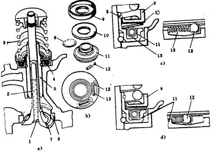
The exhaust valves of some auto mobile engines are made to rotate positively by a special mechanism during engine operation. This mechanism, known as the valve rotator, consists of a stationary housing with five ramplike grooves along its circumference that contain five steel balls loaded by return spring. Freely placed on top of the balls is a flexible washer (conespring) against which rests valve spring through the intermediary of a seating collar (Fig. 9).
Valve mechanism of an automobile engine
Fig. 9 Valve mechanism of an automobile engine
a) exhaust valve completewith valve rotator; b) valve rotator; c) valve rotator position with closed valve; d) valve rotator positoin with open valve
1-stopper; 2-hollow valve stem; 3-valve spring; 4-valve rotator; 5-valve guide; 6-insert valve seat; 7-valve face; 8-snap ring; 9-seating collar; 10-flexible washer (coneSpring); 11-valve rotator housing; 12-steel ball; 13-return spring.
As the valve is opened, spring is compressed and its increasing load causes the flexible washer to flatten out and force balls 12 down their ramps against the resistance offered by their return springs. As the balls roll down, they turn through some angle the flexible washer, seating collar 9, and valve spring together with the valve. When the valve is closed, the valve spring load decreases, the flexible washer deflects to acquire its initial conical shape and, abutting against a shoulder in housing, releases the balls which are then forced by their coil springs to return to their starting position.

In automobile engines, seating face of the exhaust valves is hard-faced with a heat-resistant alloy. Valve stem is made hollow and the cavity is filled 50 to 60% full with metallic sodium. The cavity is sealed off by stopper welded to the valve head. The metallic sodium liquefies, but does not vaporize at valve operating temperature and is capable of conducting heat much better than the valve material itself. Hence, the shaking of the liquid sodium due to the motion of the valve increases the heat transfer from the valve head to the stem and thence to the cooled region of valve guide, thus reducing the valve head temperature.

The intake valves heat less during engine operation, since they are cooled by the incoming air or fuel-air mixture on the intake stroke. To lessen the leakage (pulling) of oil into the cylinder through the clearance between the intake valve stem and its guide, some engines use an umbrella-type oil deflector cup of oil-resistant rubber placed on the valve stem. This extends over the valve guide and is held fast under the valve spring seating collar.

Valve guide supports the valve stem and guides its movement so that the valve face remains perfectly concentric with the valve seat and fits it without any skewing. Replaceable, or insert, valve guides are fabricated from cast iron or a cermet material and pressed in the cylinder head.

The intake and exhaust valve seats in many engines are formed by intake and exhaust valve seats in many engines are formed by insert rings of the heat-resistant cast iron that are pressed in the cylinder head. This facilitates their renewal during repair.

The valve spring provides the force necessary to close the valve and hold it tightly against its seat.

Valve springs may have their coils spaced either evenly or variably. Variably spaced valve springs, also known as the progressive rate springs, lessen the tendency toward surging as a result of resonance effects where such spring are used, the close-wound end (with less coil spacing) must be installed to-ward the valve had.

Some engines use two springs on each valve, which reduces the size of the springs, improves their reliability, and makes their operating conditions less arduous.

The motion-transmitting components of the valve mechanism serve to transmit motion from the camshaft to the valves. These include valve lifters, push rods, rocker arms with adjusting screws, and rocker-arm shaft with pedestals and locating springs.

Valve lifters, or tappets are made of steel. The tappets, also known as cam followers, may be either of sliding or of pivoting type. The sliding type may have a plain cylindrical or a mush-room-like form. Plain cylindrical tappets and mushroom-type tap-pets are provided with spherical seating to effect engagement with the pushrods. The bottom contact faces of these tappets may be either flat or slightly convex. To ensure a uniform distribution of wear over the face, the tappets are in duced to rotate as they reciprocate during engine operation. With flat-bottomed tappets, rotation is achieved by offsetting the tappet barrel axis relative to the cam axis, while in the case of spherical bottom tappets, this effected by making use of cams that are slightly tapered across their width, as a result of which the contact point between the tappet face and the cam is offset relative to the tappet axis.

Push rod serves to transmit force from the valve lifter to the rocker arm. Push rod may be fabricated from a solid or hollow steel bar. Push-rod ends are made in the form of either a ball or a socket and are thoroughly ground and heat treated. The lower end of the pushrod is ball-shaped. It engages the spherical socket in the valve lifter barrel. The upper end may-be either ball-or socket-shaped and it mates with the spherical socket or the convex ball on the end of the adjusting screw in the rocker arm.

The pivoting roller-type cam followers take the form of a hinged lever arm. On one end of the follower arm, there is a boss with a bore into which is pressed brone bushing to receive a hollow shaft supported in the cylinder –block-and-crankcase unit. The other end of the cam follower carries roller that rotates in a needle bearing and contacts the cam. Immediately above the roller, the follower is provided with an insert spherical seating that is press-fitted into a bore in the follower arm and engages the ball end of the push-rod.

Valve Gear

Respons: 1 comments
The valve gear of an internal combustion engine provides timely admission of the fresh charge into the cylinders and exhaust of spe gases from them. For this purpose the valves at definite moments open and close the intake and exhaust ports in the cylinder head, through which the cylinders communicate with the intake and exhaust manifolds.

The valve gear consists of timing gears, a camshaft, tappets, push rods, rockers with fasteners, valves, springs with fasteners and valve guides (see Fig. 7).
Valve gear of overhead-valve V-type engine
Fig. 7 valve gear of overhead-valve V-type engine
The timing gears in most engines are housed in a special case fitted at the front end of the engine. These are necessary to transmit rotation from the crank-shaft to the camshaft, fuel injection pump shaft, and to the oil pump, and other mechanisms. The gears are made of steel and use helical teeth to reduce noise.

Camshaft serves to open the engine valves positively and timely, in a definite sequence, and to control their closing against the return action of the valve springs.

The shaft is made integral with its cams and bearing journals. Each cam controls a single valve, either intake or exhaust. The cam profile of the exhaust-valve cams is more obtuse than that of the intake-valve cams, hence the exhaust valves stay open for a longer period than the intake ones do. Inn some automobile engines, the camshaft is made integral with fuel pump eccentric wheel and oil pump drive gear. The cam on steel camshafts is induction hardened.

The camshaft bearings are lubricated with oil supplied under pressure from the main gallery in the cylinder block. In most engines, the front end of the camshaft carries the timing gear. The camshaft gear may be fabricated from steel, cast iron or fabric-base laminate. Sandwiched between the end faces of the timing gear boss and the camshaft front bearing journal is the spacerring which is encircled by the thrust plate bolted to the front wall of the cylinder-block-and-crankcase unit to locate the camshaft axially. The ring is 0. Ito 0.2 mm thicker than the plate, and it is this difference that determines the camshaft end play.

The tappets are to transmit the force from the camshaft to the push rods. The tappets are small cylindrical bores receive the push rods. The tappets are made of cast iron or steel and located in the guides, which may be made integral with the cylinder block or removable as in the engine. With the engine running, the tappets continuously rotate about their axes for uniform wear. The rotation is ensured by a convex surface of their bottoms and a slanted surface of thd cams.

The push rods transmit the force from the tappets to the rocker and are made as steel stems with hardened tips or duralumin tubes with spherical steel tips press-fitted at both ends. The push rod tips bear against the tappet hollow at one end against the spherical surface of the rocker adjusting screw at the other.

The rockers transmit the force from the push rod to the valve. The rockers are made from steel and are installed on a hollow fulcrum a bronze bush is press fitted into the rocker hole to reduce friction. The hollow fulcrum (rocker shaft) is supported by standards on the cylinder head. End play of the rocker is prevented by a coil spring. The rocker arm is a bell crank made of steel. At the middle of the rocker arm, there is a boss with a bore into which is pressed the bushing. A hardened curved pad is provided on the end of the rocker (on its longer arm) where it contacts the valve stem tip, while a threaded hole is machined in its other end to receive the adjusting screw used to set the valve clearance, the clearance between the rocker contact pad and the valve stem tip, so that the valve will be tightly pressed against its seat when hot. The rocker arm freely oscillates about the rocker-arm shaft sunnorted by a series of pedestals, or brack-est, which are bolted to the top deck of the cylinder head.

The valves are used to open and close the intake and exhaust ports in the engine periodically, depending on the position of the pistons in the cylinders and engine firing order.

In the engines, the inlet and exhaust ports are made in the cylinder heads and terminate in inserted valve seats of heat-resistant cast iron

A valve consists of a head and stem. The valve head has a narrow chamfer of 45’ or 30’ referred to as valve face. The valve face fits tightly against the seat, which is achieved by grinding.

The heads of the inlet and exhaust valves are of different diameter. For better engine breathing, the inlet valve has a larger diameter than the exhaust one. As the valves are not equally heated in the running engine, they are made from different materials. The inlet valves are made from chromium steel, the exhaust valves are of silchrome heat-resistant steel.

The cylindrical stem of the valve has a recess at the upper end for fastening the valve spring. The valve stems slide in the castiron or cerametallic valve guides. The valve is pressed against its seat by a steel cylindrical spring.

The spring has a variable coil pitch to lessen the tendency of the spring to vibrate or “flutter” at high speeds.

One end of the spring rests on a seating collar arranged on the cylinder head, the other end bears against the spring retainer. The spring retainer is held on the valve stem by 

two tapered locks whose inner shoulder enters into the recess in the valve stem.

To decrease oil penetration along the valve stem to the combustion chambers, the seating collars are fitted with rubber rings or the stems are provided with rubber caps. More uniform heating and wear of the valve are ensured with “free valves”, i.e. the valves rotating during the operation of the engine.

Crankshaft and Flywheel

Respons: 3 comments
Crankshaft and Flywheel
The crankshaft assembly includes the crankshaft and bearings, flywheel, harmonic balancer, gears, and front and rear oil seals.

The crankshaft converts the reciprocating motion of the pistons to rotary motion of the crankshaft. All the power produced by all the cyliders is transferred to the crankshaft. The crankshaft transmits it to the flywheel or torque converter.

The flywheel or torque converter helps the engine to run smoothly by absorbing some of the energy during the power stroke and releasing it during the other strokes.
The vibration damper (harmonic balancer) dampens crankshaft torsional vibrations that result from the power impulses. As each cylinder fires, it causes the crank throw for that cylinder to speed up. The rest of the crankshaft tends to stay slightly behind, causing a twist. This causes torsional vibrations, which are dampened or partially absorbed by the vibration damper.

The crankshaft is supported by split-type (two-piece) precision bearing inserts that reduce wear and friction.

The front and rear crankshaft seals prevent oil leakage past the rotating crankshaft.

Crankshafts are of forged steel construction and induction-hardened for durability and wear resistance.

A flange at the rear of the crankshaft provides the means for mounting the flywheel or converter drive plate.

The flywheel contributes to the uniform rotation of the crankshaft and helps the engine overcome loads when starting the automobile from rest and also during operation. Even though the power impulses of a multicylinder engine follow each other or overlap, additional smoothing out of the power impulses is desirable. The engine flywheel does this job. The flywheel is a relatively heavy metal wheel which is firmly attached to the crankshaft. Because of its rotation the flywheel acquires kinetic energy; when the flywheel speeds up, it stores additional kinetic energy, and when it slows down it gives back that energy. The amount of energy which a flywheel will store for a given change in speed depends on its inertia, which, in turn, depends on its mass and its effective diameter. The energy which the engine pistons deliver to the crankshaft fluctuates, being greatest when a piston has started on its power stroke, much less on the exhaust and suction strokes, and negative during the compression stroke. These fluctuations in energy to and from the crankshaft.

Cause corresponding fluctuations in its speed; the effect of the flywheel is to reduce the speed fluctuations by storing energy when the crankshaft accelerates and giving it back when the shaft starts to slow down. The heavier the flywheel or the larger its diameter the smaller will be the speed changes.

The flywheel resists any sudden change of crankshaft (engine) speed. Thus, when a power impulse starts (with its initial high pressure), the crankshaft is given a momentary hard push (through the connecting rod and crankshaft). But the flywheel resists the tendency of the crankshaft to surge ahead. Thus, the momentary power peaks are leveled off so the engine runs smoothly.

Since the flywheel also serves to form part of the engine clutch, its rear face is thoroughly machined. In the front face of the flywheel, there is a shallow indentation used to determine the position of the piston in the first cylinder. When this indentation is aligned with a special hole provided in the bell housing, the piston is at top dead center (TDC). In some engines, this indentation indicates the start of fuel injection into the first cylinder. The flywheels of some engines also carry marks indicating the serial numbers of the cylinders where the compression stroke occurs. The flywheel marks and indentation are used for setting the valve and ignition systems relative to prescribed positions of the crankshaft.

In addition, the flywheel has teeth on its outer edge; the electric-starting-moto pinion teeth mesh with these teeth when the engine is being cranked for starting.

A flywheel ordinarily is mounted near the rear main bearing. This is usually the longest and heaviest of the main bearings, since it must support the weight of the flywheel.

The purpose of the flywheel is to assist the engine to idle smoothly by carrying the pistons through parts of the operating cycle when power is not being produced.

The heavier the engine flywheel, the smoother the engine will idle. However, because of its inertia, an excessively heavy flywheel will cause the engine to accelerate and decelerate slowly. For this reasort, heavy, duty or truck engines have large and heavy flywheels. While racing engines or high performance engines have light flywheels.

The rear surface of the flywheel is usually machined flat. This surface is used to mate with one surface of the clutch. With automatic transmissions, where no clutch is used, part of the fluid flywheel or torque converter is attached to and becomes a part of the flywheel.

For an engine of a given horsepower, the energy variations during a complete cycle are greatest if the engine has only one cylinder. Single-cylinder engines, therefore, require large flywheels to keep the momentary speed variations within reasonable limits. In multicylinder engines the energy changes become less as the number of cylinders increases. The reason is that not only are the cylinders smaller but also that their impulses are more frequent and, in the case of engines with many cylinders, one piston delivers power at the same time as another is on compression. Consequently, the required size of the flywheel becomes very small. The cranks, crankpins and large ends of the connecting rods have considerable rotating weight and exert the same inertia effect as a flywheel. So does the rotor of a connected electric generator. Therefore, in some large multicylinder engines, flywheels are not necessary and hence are not used.

Connecting Rods and Crankshaft

Respons: 0 comments
     The connecting rods link the pistons with the crankshaft and transmit to it the loads arising from the combustion gas pressure taken by the pistons. In operation, the connecting rod is subjected to both gas pressure and inertia loads, and therefore, it must be adequately strong and rigid and light in weight as well. Connecting rods are generally fabricated from a high quality steel in the form of a bar with ring-shaped heads at its ends, the heads being known as the connecting rod big end and small end and serving to attach the rod to the crankpin and the gudgeon pin of the piston, respectively.
     Shank, or blade, 3 of the connecting rod is provided with an lcross section to give the rod maximum rigidity with the minimum of weight. The small end of the connecting rod is made in the form of a continuous eye into which bronze bush 2 is pressed so as to provide an interference it, whereas the big end of the rod is split into halves with the upper half integral with the rod shank and the lower half in the form of detachable cap 6 (Fig. 5).
     The bore in the big end of the connecting rod is machined after the cap is assembled on the rod. Therefore the rod caps must not be interchanged. To avoid misplacing the rod caps during assembly, the connecting rods and their mating caps are marked on one side with serial numbers starting with the first rod from the radiator, to identify their location in the engine.
Connecting rods
Fig. 5 connecting rods
a)connecting rod components; b)cross-sections through connecting rod shanks (blade) and methods of feeding oil to piston pin; c)angled connecting rod big end; d)methods of locating connecting rod cap
1-connecting rod small end; 2-connecting rod bush; 3-connecting rod shank (blade); 4-connecting rod big end; 5-connecting rod bearing half-liner (insert); 6-connecting rod cap; 7-cotter pin; 8-horned nut; 9-locating lug; 10-connecting rod bolt; 11-oil hole; 12-oil passage; 13-serrated joint; 14-tab washer.
Both halves in the big end of the connecting rod are joined by means of special high-strength bolts 10 and nuts. The nuts on the connecting rod bolts are tightened with a torque indicating wrench and then cottered. The big end of the connecting rod houses a sliding contact bearing comprising two half-liners, or inserts 5. The half-liners are kept from shifting endwise or rotating by locating lugs’, or locking lips, 9 that nestle in special slots provided in the housing on one side of the rod. The big end of the connecting rod of automobile engines features a hole through which oil is squirted onto the cylinder walls.
     The oil necessary to lubricate the piston pin is supplied either through oil hole 11 or via oil passage 12 drilled through the connecting rod shank.
     The parting line between the connecting rod and its cap is generally arranged at right angle to the axis of the shank, but in some engines, the parting line is necessarily arranged diagonally, because the proportions of the big end of the connecting rod are such that the lower part of the rod could not otherwise be passed through the cylinder for assembly purpose. With such an angled big end, the cap is secured to the connecting rod by setscrews instead of bolts and nuts. To resist the greater tendency for the inertia forces to displace the cap sideways relative to the connecting rod, either a serrated or a stepped joint is generally preferred for their abutting faces. Hence, the retaining setscrews in their clearance holes are completely relieved of shear loads. Tab washers 14 are used under the heads of setscrews in order to prevent the latter form working loose.
     The crankshaft takes the downward thrusts of the pistons and connecting rods when the fuel-air mixture is burned in the cylinders and changes these thrusts into torque which is transferred to the drive line of the automobile; it also drives various engine mechanisms and components,. The periodic gas pressure and inertia forces taken by the crankshaft may cause it to suffer wear and bending and torsional strains. The crankshaft therefore must be adequately strong and wear-resistant. 
     The crankshaft is either forged from a high-quality steel or cast in a high-strength iron. It consists of main bearing journals (Fig.6) 1, crankpins 11, webs, or cheeks, 2 that connect the journals and crankpins together, a nose (front end), and a shank (rear end). Counterbalance weights 12 necessary for balancing the crankshaft are either formed integrally with, or attached separately to, the crank webs. The main bearing journals and crankpins are induction hardened to improve their wear resistance. Drilled diagonally through the crank webs are oil holes to supply oil to the crankpins. The crankpins are bored hollow in order to reduce the crankshaft inertia. The open ends (or end where angular blind holes are necessary to clear counterbalance weights are sealed by screw plugs 17, since the hollow interior c of each crankpin also acts as an oil supply duct for big end lubrication and as a centrifugal oil cleaner. With the crankshaft rotating, mechanical impurities *wear products) contained in the oil inside the hollow crankpins settle on the crankpin interior walls under the action of centrifugal forces. In V-type engines, each crankpin has two connecting rods assemble on it, and therefore, the crankpins here are longer than in in-line cylinder engines. The crankshaft front end carries one or two gears for driving the valve mechanism and also other engine mechanisms, fan drive pulley 16, and a starting crank jaw (ratchet) or bolt is. Mounted between the crankshaft pulley and gear is oil slinger 6 that throws oil away from the crankshaft front bearing seal. In some engines, the crankshaft gear is carried on the rear end of the shaft.
Crankshafts
Fig. 6 crankshafts
a) of in-line tractor engine; b)of v-type automobile engine
1-main bearing journal; 2-web (dieek); 3-thrust half-washers; 4-main bearing cap insert; 5-flywheel; 6-oil slinger; 7-dowel; 8-flywheel bolt; 9-flywheel ring gear; 10-main bearing saddle insert; 11-crankpin; 12-counterbalance weights; 13-crankshaft gear; 14-oil pump drive gear; 15-bolt; 16-fan drive pulley; 17-screw plug; 18-clean oil outlet tube; 19-crankshaft flange; A-crankpin size group marking; B-oilway to crankpin hollow interior; O-crankpin hollow interior.
     Attached to the rear end of the crankshaft is flywheel 5. In some engines, the flywheel is located relative to the crankshaft by dowels 7 and clamped firmly to the rear face of the shaft by a ring of bolts 8 screwing directly into the shaft end. Other engines have their crankshafts provided with flange 19 in which holes are drilled for securing the flywheel. In front of the flange, the crankshaft is provided with an au return thread which, in conjunction with a close clearance plain bore housing, forms a labyrinth-type seat operating upon the Archimedean screw pump principle to oppose the leakage of oil into the bell housing.

Engine pistons serve several purposes

Respons: 1 comments
(1) Transmit force of expansion to crankshaft through connecting rod.
(2) Act as a guide for upper end of connecting rod.
(3) Serve as a carrier for piston rings use to seal piston in cylinder.
(4) Aid in the burning of the fuel mixture by introducing a swirling action to the air/fuel mixture. (This is particularly true in the case of diesel engine pistons). The swirling is accomplished by altering the contour of the piston head.
Engine pistons serve several purposes
Pistons operate under exceedingly difficult mechanical and thermal (heat) conditions, so they must be made and installed with the utmost care. Piston must be strong enough to stand the force of the expansion, yet light enough to avoid excessive inertia forces when their direction of travel is reversed twice each revolution.

Pistons must be able to withstand the heat from the burning air/fuel mixture, plus the heat generated by friction. They must slide freely in the cylinder. If fitted too tightly, the engine will over-heat and/or seize. If fitted with too much clearance in the cylinder, the piston will knock and rattle.

The piston head or “crown” is the top surface against which the explosive force is exerted. It may be flat, concave, convex or any one of a great variety of shapes to promote turbulence or help control combustion. In some applications, a narrow groove is cut into the piston above the top ring to serve as a “heat dam” to reduce the amount of heat reaching the top ring.

Piston rings carried in the ring groove are of two basic types: “compression” rings and “oil control” rings. Both types are made in a wide variety of designs.

The upper ring or rings are to prevent compression leakage; the lower ring or rings control the amount of oil being deposited on the cylinder wall. The lower groove or grooves often have holes or slots in the bottom of the grooves to permit oil drainage from behind the rings.

The piston ring lands are the parts of the piston between the ring grooves. The lands provide a seating surface for the sides of the piston rings.

The main section of the piston is known as skirt. It forms a bearing area in contact with the cylinder wall which takes the thrust caused by the crankshaft.

Some thrust is created on both sides of the piston. “Major” thrust is to the side opposite to the crank throw as it is driven down on the power stroke. “Minor” thrust is the side opposite to the crank throw as the piston moves up on the compression stroke. Pistons are internally braced to make them as strong as possible.

The piston pin (wrist pin) in the piston bosses may also serve as a bearing for the piston, and it may not be located exactly in the middle of the piston. It may be placed as much as 1/16 inch to one side to lessen side thrust of the piston on the cylinder wall.

In some designs, the piston skirt is extended downward on th thrust sides to form what is known as a “slipper” piston. This design feature increases the area of piston contact with the cylinder walls at the thrust faces.

Some pistons are also cut away, or partially away, around the piston pih holes. This “relief” is intended to provide additional clearance to avoid “seizing” if the piston should become overheated and expand excessively.

High compression for starting and lower compression under load is highly desirable for diesel engines. One method of attaining this goal is the variable compression ratio (VCR) piston.

One form of VCR piston has been developed that provides improved starting, better idling and improved output per cubic inch of displacement. Comparisons were made of a VCR piston engine and a conventional engine of the same displacement and same general design. Tests indicated a gross bake horsepower (bhp) for the conventional engine of 550. The engine with VCR pistons produced 1475 bhp.

Other variable compression ratio components include the connecting rod, which is modified to allow engine oil to transfer from the connecting rod bearing through a slipper to the inner piston. The outer piston corresponds to the normal piston in that it contains the combustion chamber and oil rings. The inner piston is an aluminum forging and contains the valves and hydraulic sealing rings. It is connected to its rod by the piston pin in the conventional manner.

The entire assembly of inner and outer pistons is limited n travel by the piston retaining ring, which provides a mechanical stop for upward motion of the piston.

As engine power and combustion pressures are increased, the pressure on the oil in the upper chamber is also increased.

When this pressure exceeds the setting of the spring-loaded discharge valve, a small amount of oil passes to the crankcase, and the outer piston moves downward. This movement results in an increase in clearance volume between the outer piston and the cylinder combustion dome. Which reduces the compression ratio. This process continues until the upper piston contacts the inner piston, preventing any further reduction in the compression ratio.

Engine Construction

Respons: 11 comments
The automobile engine is essentially a heat engine. The heat engines used in modern automobiles are internal combustion engines. Each of this engine has a few main working parts; the auxiliary parts are necessary to hold the working parts together or to assist the main working parts in their performance. The main parts are: (a) the engine block; (b) the cylinder; (c) cylinder head, usually holding in-let and exhaust valves; (d) the piston; € the connecting rod; (f) the crankshaft; (g) the crankshaft or main and connecting-rod bearing; and (h) the fuel pump and fuel nozzle.

The engine block forms the main framework (Fig. 4), or foun-dation, of the water-cooled engine. The block is mainly cast from gray iron or iron alloyed with other-metals such as nickel or chromium. However, some blocks have been made from aluminum. In any case, the block itself has many components cast into it or assembled onto it.

Cast into the block, for example, are the cylinders. The cylin-ders are circtjlar, tubelike openings in the block, which act as guides for the pistons as they move up and down. Engine blocks have four, six, or eight openings, or cylin-ders. In aluminum blocks, the cast-iron or steel cylinder sleeves (liners) are installed because these metals can withstand the wear caused by the moving pistons better than aluminum can.
Types of cylinder blocks
Also cast into the block are the water jackets. The water jackets are open spaces between the inner and outer surfaces of the block and cylinders through which the coolant flows. The coolant, in turn, removes heat from the metal surfaces around such areas as the cylinder walls and valve seats and carries the heat to the radiator where it releases into the air. Cast-iron blocks usually have a number of holes along the side and in the end leading into the water jackets.Finally, the block has cast-in bores for both camshaft and crankshaft. The crankshaft bore has a machined finish, which accommodates a bushing that actually supports the revolving shaft in the block. However, only haft the crankshaft bore is cast into the block. The other half is ma-chined into a bearing cap. The block bearing saddles (the halt bores) and the caps also have a machined finish, which accommodates the main bearings, which in turn support the crankshaft.

Many parts also attach by fastening devices to the average engine block. These items include the water pump, oil pan, timing gear or chain cover, the flywheel or clutch housing, the ignition distributor, Oil and fuel pump, and the cylinder head. The water pump is a component of the cooling system. The crankshaft usually rotates this unit by means of a belt. When revolving, the water pump circulates coolant between the engine water jackets and the radiator.

The oil pan and the lower portion of the block together are known as the crankcase; they enclose or encase the crankshaft. The oil pan is usually formed of pressed steel. The pan itself is also a reservoir, which usually holds 4 to 9 quarts of lubricating oil, depending on the design of the engine.

When the engine is operating, the oil pump of the lubri-cating system draws oil from the pan and pumps it to all the moving parts of the engine. Alter the oil lubricates these parts, it drains off and runs back down into the pan. Consequently, there is a constant circulation of oil between the pan and the moving parts of the engine.

The timing gear or chain cover, as its name implies en-closes and protects the timing gears or timing chain and sprockets from foreign materials. This cover, like the oil pan, can be formed from pressed steel. However, in some cases. The cover will be formed from cast iron or aluminum because these particular covers have not only the fuel pump but also the water pump attached directly to it and have coolant flowing through special passages formed into the cover.

In addition, the cover has a machined area that accommodates the timing-cover seal. The seal prevents leak-age of lubricating oil from around the area where the crankshaft protrudes through the cover to the outside of the engine. The seal itself is a lip type bonded to a steel backing that presses into the machined bore in the cover.

The detachable flywheel or clutch cover encloses and protects the flywheel and the clutch assembly. This cast-iron or aluminum component also supports a portion of the clutch linkage and provides the mating-surface area to which the transmission attaches.

The ignition distributor usually attaches to the block via a c shaped clamp and a cap screw and serves two basic functions. First.it closes and opens the electrioai circuit between the battery and the ignition coil. When the points close and completes this circuit battery current flows into the coil and permits the coil to build up a strong magnetic field. As the points open. The circuit opens and the magnetic field in the coil collapses, which causes the coil to produce a high-voltage source of current. The second task of the distributor is then to direct each high voltage surge to the correct spark plug at the correct instant in the engine cycle by the distributor rotor cap, and secondary wiring.

The oil pump usually mounts to the upper crankcase area of the block. The camshaft usually drives both the oil pump and distributor by a spiral gear. As mentioned the task of the oil pump is to draw lubricating oil from the pan and force it to all the moving parts of the engine.

The camshaft also activates the timing cover or block mounted mechanical-tye fuel pump. This pump is actually part of the fuel system. Its function is to transfer fuel from the fuel tank to the carburetor.

Copyright © Automobile Engineering.

Designed By: