During operation, the load on the engine of an automobile frequently varies, depending on the ambient conditions (lay of the ground, soil condition, etc.). These load variations cause the engine speed to change accordingly, provided the position of the throttle valve or fuel control rack remains unchanged.
When the load on the engine is decreased, the engine speed may rise beyond safe limits, causing accelerated wear of the engine working parts and increased fuel consumption. A device for automatically controlling the speed of an engine by regulating the intake or injection of fuel, so that the engine speed is maintained at the desired level under all conditions of loading, is termed the governor.
Governor control may be effected by centrifugal (mechanical), hydraulic, pneumatic or combined (pneumatic-centrifugal) means. Speed governors may be classed as speed-limiting, constant-speed or all-speed. Speed-limiting and constant-speed governors are used on automobile engines and on auxiliary engines employed for starting tractor diesel engines. An automobile governor is in essence a maximum-speed governor.
The automobile maximum-speed governor is of pneumatic-centrifugal type. It comprises two mechanisms: centrifugal governor sender and diaphragm-operated governor actuator. The centrifugal governor sender includes a rotor whose shaft receives the rotation from the engine camshaft. The sender unit is mounted on the timing gear cover. The rotor houses the valve which is pulled away from its seat by a spring.
The governor actuator includes a diaphragm which is connected by a rod to one end of the bell-crank. The other end of the bell-crank is connected with the governor spring. The bell-crank is fixed to the throttle spindle. The throttle control mechanism incorporates a special claw coupling which enables the governor actuator to close and open the throttle valve irrespective of the position of the accelerator pedal. The spaces above and below the diaphragm are interconnected through the governor sender by pipes. On the other hand, the space above the diaphragm communicates with the carburetor chamber below the throttle valve and that below the diaphragm, with the space below the choke valve, via passages.
So long as the engine speed remains below the preset maximum (3200 rpm), the centrifugal force of the valve is insufficient to overcome the tension of the spring, and so the valve stays open. As a result, the space above and below the diaphragm communicate with each other through the governor sender. When the maximum speed is attained, the centrifugal force of the valve overcomes the resistance offered by the spring, and the valve closes ott to its seat, thus breaking communication between the spaces above and below the actuator diaphragm. This action causes the depression communicated from the carburetor chamber to the space above the diaphragm, via the lower passage, to grow higher. If the engine speed increases further, this depression becomes sufficiently high for the diaphragm to deflect upward against the governor spring force and close the throttle valve cy a certain amount, thus reducing the engine speed.
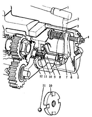
The main component parts of the governor are a housing, a shaft with a drive disk, a spring, and ball-shaped weights (balls) (Fig. 9)
The Governor housing is held to the engine crankcase through the medium of an adaptor plate. The governor shaft notates together with the drive disk whose slots accommodate balls that are sandwiched between the thrust washer and the conical shaped movable disk.
The movable disk is pressed against the balls by the bell-crank loaded by a spring. Rigidly fixed on the pivot pin of the bell-crank is the external governor lever which is connected with the throttle rod. When the engine is not operating, the spring forces the movable disk to the extreme left-hand position and the throttle nod, to the extreme right-hand position. With the throttle rod in this position, the throttle valve is fully open. During engine operation, the centrifugal forces of the rotating balls cause the balls to move outward against the spring force and displace the movable disk to the right and the throttle rod to the left, thus closing the throttle valve.
With a ready load on the engine, an equilibrium exists between the centrifugal force of the rotating balls and the governor spring force. If the load on the engine is increased, the engine speed, hence the governor shaft speed, starts dropping. In this case, the centrifugal force of the balls decreases, and the governor spring, acting through the bell-crank, moves the throttle rod to the right to open the throttle valve. As a result, the engine speed rises until its nominal value is reached. As the engine load is reduced, the engine speed rises accordingly. The centrifugal force of the rotating balls then increases and, overcoming the governor spring force, moves the throttle rod to the left to close the throttle valve. This causes the engine speed to drop down to the nominal value.
The desired engine speed is set by varying the preload on the governor spring by means of adjusting the screw. This is done at the factory, after which the screw is locked in place by a lock nut and sealed.


No comments:
Post a Comment